Process Flow Diagram for Urea Production with Full Liquid Recycling
Scene 1 (0s)
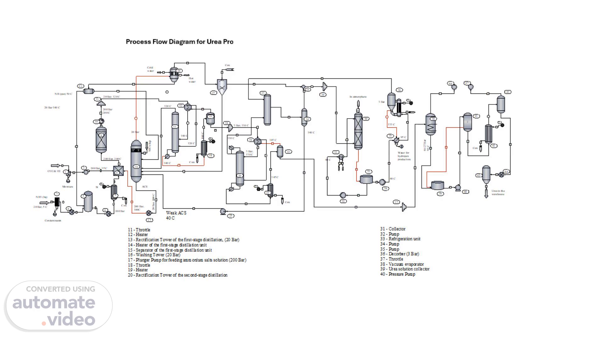
Process Flow Diagram for Urea Production with Full Liquid Recycling.
Scene 2 (11s)
[image] 02 203=5 c ZOOC 2m Bar 110 c 140 C weak ACS 40 c.
Scene 3 (1m 18s)
Pure gaseous ammonia from the washing column at a temperature of 50°C enters the First-Stage Condenser (26), where it is condensed and discharged into the Ammonia Collector (5) for return to the cycle. The liquid phase from the washing column, which is a solution of ammonium salts concentrated due to the absorption of CO2 and NH3 with a temperature of 105°C, enters Plunger Pump (17) and is supplied to the mixer under a pressure of 200 bar. Gases with a small ammonia content that are not condensed in the condensers of the first and second stages are sent to Absorber (30). The liquid phase after Separator (15) is throttled to a pressure of 3 bar and added to the second-stage distillation unit, consisting of a Heater (19) a Rectification Tower (20), a Heater (21), and a Separator (22). When throttling, the temperature of the liquid phase decreases to 110°C. Before, the liquid phase enters Rectification Tower (20), it is heated in the Heater (19) to 130°C by gases coming from Separator (22) at a temperature of 145°C. From the Tower (20) liquid phase feeding the heater (21), in which it heated by steam to 145°C. In the Heater (21) ammonium carbamate is finally decomposed, and excess ammonia is distilled off from the solution. From Heater (21), the vapor-liquid mixture enters Separator (22), where the liquid phase is separated from the gaseous one. The liquid phase is a 72% urea solution and is sent for processing into the finished product. The gaseous phase returns to the bottom of the distillation column, where it, having given up part of the heat to heat the solution from 110 to 130°C, goes to the second-stage Condenser (23). Here, water vapor is condensed due to the absorption of CO2 and NH3, and the condensate forms a weak solution of ammonium salts, which is returned by Pump (25) for concentration into Washing Column (16) and then into Mixer (8)..
Scene 4 (2m 25s)
Gases are purified from ammonia before being released into the atmosphere using a system consisting of an Absorber (30) and a Desorber (36). Unabsorbed gases with small admixtures of ammonia from the condensers of the first and second stages enter Absorber (30), which is irrigated with steam. The weak solution of ammonia and ammonium salts formed in the absorber is then sent to Desorber (36), where ammonia is separated from the solution and returned to the second-stage condenser. Water from the Desorber, containing small impurities of ammonium carbonate, is sent to reverse osmosis for purification. The purified water is then used in hydrogen production. Finally, gases purified from ammonia are released from the absorber into the atmosphere. The liquid phase from the Second-stage Separator (22) enters the Vacuum Evaporator (38), where due to self-evaporation it condenses to 76%. Then, in film-type Evaporators (42) and (43), the solution is evaporated to 98.5%. The melt is then sent to the Granulation tower (45) and subsequently to packaging..