Page 1 (0s)
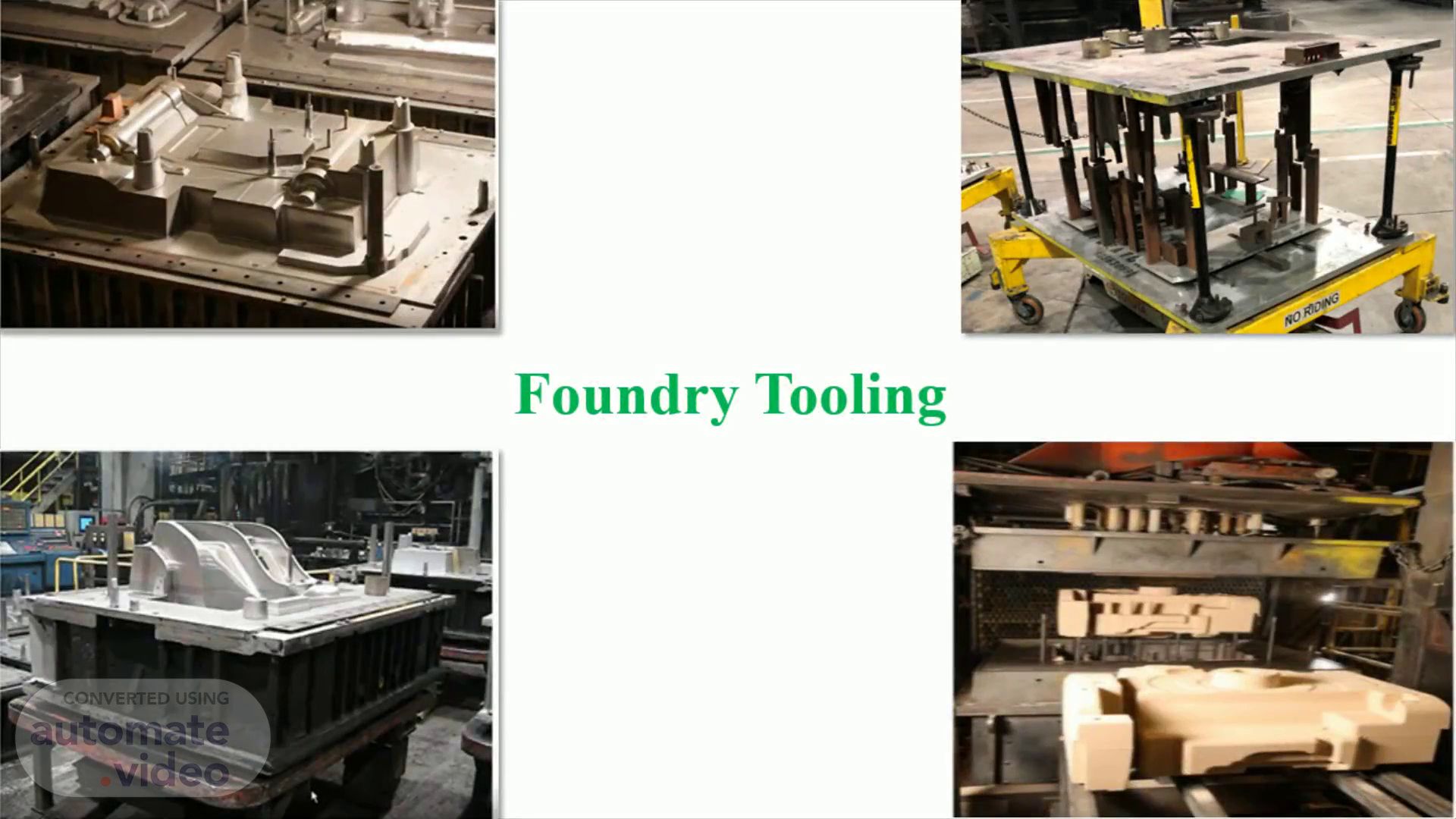
[Audio] This training helps you to understand the Foundry processes and the tooling involved in it..
Page 2 (7s)
[Audio] These are the contents of this training. Each content will be discussed in subsequent sections..
Page 3 (24s)
[Audio] The purpose of this training is to give an overview of the casting process, tooling involved in the Foundry, tool design considerations, casting defects and casting quality testing. Casting process is the economical way of manufacturing complex geometrical parts. The quality of the casting depends on the tooling along with the material chemistry, process and other parameters. In this training, some design considerations are provided for the sandcasting tool design..
Page 4 (57s)
[Audio] Casting is a process in which molten metal flows by gravity or other force into a mold where it solidifies into the shape of the mold cavity. Casting process mainly involves melting the metal, pouring it into mold, letting it freeze to have a raw casting. Foundry is a factory equipped for making the molds, melting and handling the molten metal, performing the casting process, and cleaning the finished casting. The workers who perform casting are called Foundrymen..
Page 5 (1m 29s)
[Audio] Casting can be done using both Ferrous and Non-Ferrous metals. Different alloys are considered for the casting based on their applications as shown in the table. In nonferrous, the alloys of Aluminum, Copper, Magnesium, Titanium, Zinc are predominantly used for the castings, and in ferrous, the alloys of Cast Iron and Steel are used. Aluminum alloys are used for their lightweight structures with higher dimension accuracy properties. Copper alloys like Brass and Bronze are used for their good conductivity, corrosion resistant properties and, they are used for decorative purposes. Magnesium alloys are used as they have higher strength to weight ratio properties. Titanium alloys are used for their properties like corrosion resistance, erosion resistance and heat resistance properties, also they are having good weight to strength ratio. Zinc alloys are used for their manufacturability to good surface finish, so these are used for decorative purpose. Cast Irons are used for their properties like higher strength, ductility, vibration dampening, Abrasion and wear resistance, Corrosion resistance, High temperature strength. Steel alloys like carbon steel, low alloy steel and high alloy steel are used for their properties like design flexibility, larger weight range, larger working temperature range, dynamic stability.
Page 6 (2m 59s)
[Audio] The casting process can be done in multiple ways and the major types of casting process are Permanent mold casting process, Die casting process, Investment casting process, Sand casting process and Lost foam casting process. Each process is dedicated to different applications based on the casting metal, casting size, tooling requirement etcetera. The sand-casting process and the die casting process are the important processes which have been used for John Deere products and in the subsequent sections the details of these casting processes are discussed..
Page 7 (3m 36s)
[Audio] As mentioned in previous section, each casting process is compatible to produce the castings with specific shape, weight range, metals and for the specific applications. The permanent mold casting process is used for producing simple shaped castings with a weight ranging from 57 grams to 300 kilograms. Here, the alloys of Aluminum, Copper and Magnesium are used. The die casting process is used for producing simple to moderate shaped castings with a weight ranging from 20 grams to 227 kilograms. Here, the alloys of Aluminum, Lead, Magnesium, Tin and Zinc are used. The investment casting process is used for producing moderate to complex shaped castings with a weight up to 227 kilograms. Here, the alloys of steel, Carbon steel, cast iron, stainless steel, Aluminum, copper, Magnesium and Nickel are used. The sand-casting process is used for producing simple to moderate shaped castings with a weight up to 450 tons. Here, the alloys of steel, Carbon steel, cast iron, stainless steel, Aluminum, copper and Nickel are used. The lost foam casting process is used for producing simple to moderate shaped castings with a weight up to 454 kilograms. Here, the alloys of cast iron, and Aluminum are used. Eventually each casting process is meant for some product applications as shown in the last column of this table..
Page 8 (5m 17s)
[Audio] The sand-casting process involves the following steps. Step 1. A pattern which has the shape of the desired casting is placed in sand to make an imprint. A gating system is incorporated into the pattern to feed the molten metal and the risers may also be used to compensate for shrinkage during solidification. Step 2. The core package creates the internal geometry of the casting, and it is to be placed in the mold at a specified location. Step 3. The pattern is removed, and the mold cavity is filled with molten metal by gravity pouring. Step 4. The Molten metal is cooled. Step 5. The sand mold is broken away and the casting removed..
Page 9 (6m 11s)
[Audio] The Die casting machine could be a hot chamber or cold chamber machine. The hot chamber die cast machine is used for Zinc, Tin and other low melting point metals. The Die casting process involves the following steps. Clamping is the first step in which the preparation and clamping of the two halves of the die is done. After cleaning and lubrication, the two die halves are clamped together to create the cavity. Injection is the second step in which the molten metal is injected into the die. The injection is used in pressure die casting process but in gravity die casting the molten metal is just poured into the cavity without the aid of any pressurized mechanism. Cooling is the third step in which the metal begins to solidify once it enters the die's cavity. Ejection is the fourth step in which the die halves are opened, and the casting is ejected. Trimming is the last step in which excess material is trimmed. This excess material results from the material in the channels of the die during cooling. The excess material must be trimmed, and the trim scrap is recycled..
Page 10 (7m 28s)
[Audio] A Foundry with sand casting process have four important sections like Core, Mold, Melt & Clean. In core section, the core is manufactured in the core box. Here, the sand (with or without binder) is injected into the cavity to take the shape, then the finished core is taken out from the core box. In mold section, the mold is prepared using the pattern, core and other elements. The mold have cavity which is created by the pattern impression and the core is placed in the core print locations. The cavity creates the external geometry and core creates the internal geometry of the casting. In melt section, the molten material is produced in furnace. The molten metal has the ingredients of base metal and alloys in required proportion. In clean section, the solidified raw casting is cleaned to remove unwanted materials..
Page 11 (8m 28s)
[Audio] The tooling are the devices or components which eases the manufacturing process. In this training, the tooling for the sand-casting process will be discussed in detail. In foundry also the tooling plays an important role in producing the quality castings. The tooling must be designed to produced a casting to meet quality requirements and cost targets. Tooling design process involves, The number of impressions per mold is determined in the quoting process Tooling designers locate the impressions in the mold and add gates and risers to the system Designers develop tooling to create cores if those are needed In mold section and core section the requirement of tooling quite prominent. In the mold section, Pattern design, match plate design and mold box design are important. In core section, core box design, core setting fixture, core handling devices are important..
Page 12 (9m 34s)
[Audio] Core and Casting assembly or CC assembly is the preliminary activity in Tool design for the sand-casting process. CC assembly is the digital reference for the rest of all tooling designs, like pattern design, gating design, core and core box design. The creation of CC assembly follows an order as follows Applying the shrink rates to the raw casting model, the resulting model is called cash model Extract the core features from the cash model Providing the core prints with all drafting Establish the parting surface for the casting Assembly of the extracted core and casting to make final CC assembly The CC assembly will be used for the gating design and simulation. If any gating arrangement that fouls with the core prints is observed, then the core print geometry needs to be modified..
Page 13 (10m 36s)
[Audio] In sand casting process, the mold is prepared, and the molten metal is poured into the molten to create the casting. The mold box has two halves, the upper half cope and the lower half drag and in which the cavity and core are confined to manufacture the casting. The cavity creates the external geometry of the casting, and this cavity is created by the pattern impression. The core creates the internal geometry of the casting, and it is placed in the mold in core prints which are also created by the pattern. The core can be a single piece or a package with multiple cores..
Page 14 (11m 16s)
[Audio] A mold is a form or a box or a shell, which defines and contains the cavity for which molten metal is poured into. That cavity is filled with liquid metal and allow it to solidify to get the casting. Mold boxes are of two categories namely, expendable mold and reusable mold. In Expendable mold, there are a few types are there namely green sand mold , Co2 mold, No baked mold, and shell mold. In this training we are discussing more about green sand mold. Mold is usually made from sand, plaster, ceramic powder mixed with binder. Some basic terminologies of the mold are 1. Flask: It is the box which holds the halves together 2. Parting line: It separates the cope and drag halves 3. Mold cavity: It is formed by packing sand around a pattern which has the shape of the part. When the pattern is removed, the remaining cavity of the packed sand has the desired shape of the cast part. 4. Core: It is generally made of sand, used when casting has an internal surface, and it defines the interior geometry of the casting part 5. Gating system: It is the channel through which molten metal flows into the cavity from the outside of mold and it consists of down sprue 6. Down sprue: It is the passage through which molten metal enters a runner leading to the main cavity 7. Pouring cup: It is the entrance which is at the top of the down sprue. It minimizes the splash and turbulence as metal flows into the down sprue 8. Riser: It is a reservoir in the mold which is a source of liquid metal to compensate for shrinkage of the part during solidification. The riser must be designed to freeze after the main casting in order to satisfy its function..
Page 15 (13m 37s)
[Audio] Pattern is a replica of the final casting The Patterns can be made up of many materials, like wood, metal, plastic, wax, Expanded Poly Styrene The Wood patterns are Cheap and can be easily machined but they are prone to warping, swelling, unstable and wear out easily. The Metal patterns are more expensive, but they are stable, accurate and durable. Typically, aluminum, cast iron or steel are used for metal patterns. The Plastic patterns are usually made up of Epoxy and Polyurethane. The plastic patterns are easy for preparation, and they are stable with good durability. The Wax patterns are used for investment casting. In investment casting, these patterns melted out before casting. The Expanded Poly Styrene patterns are Pre-expanded beads blown into mold and they are heated to completely fill the mold and bond the beads. These Pattern are burnt out by molten metal. Type of the Pattern depends on the complexity of the casting as well as the number of castings required from the mold. Based on these, patterns are of mainly four types, namely Single piece or solid pattern, split pattern, Match-plate pattern, Loose piece pattern. Single piece patterns are the simplest, cheapest and using for slowest molding. These types of patterns are suitable for the simple casting with low volume requirements. Split Patterns are split into two parts where the parting line will be. It molds the drag first with bottom part of the pattern and, invert then add the top half of the pattern to molds the cope. Another way is, each part of the mold like, cope and drag can be molded separately, then joined. These types of patterns are suitable for large castings with higher volume requirements. Match Plate Patterns are the plate with the cope pattern on one side and the drag pattern on the other side with locating pins and holes. It can include runners and gates, and these can be made from wood and joined or machined or cast from metal. These types of patterns are suitable for small to medium size castings with higher volume requirements. Loose Piece Patterns are special patterns. These Patterns are assembled from different pieces held together with pins and the same pieces are withdrawn sequentially after the pin is removed. These patterns are suitable for very complex shape castings, but they are expensive..
Page 16 (16m 21s)
[Audio] Shrinkage allowance: As the molten metal cools and solidifies in the mold, the natural shrinkage occurs. The dimension of the casted product gets reduced as compared with the mold cavity. The amount of shrinkage depends upon the type of metal. In order to compensate the shrinkage allowance for outer dimension, the size of the pattern is made over size and for inner dimension like hole; the pattern is made under size. The different materials experience the different value of shrink rate as shown in the table. Draft: For easy removal of a pattern from the molding sand, some degree of taper or drafts are provided. With the provision of little or no draft, there are chances that the pattern may damage the mold rather than slipping out smoothly. Various factors are responsible for selecting the proper drafts like, method of molding and drawing of the pattern, pattern material, surface smoothness and degree of precision. A small draft of 0.5 degree to 2 degree should be provided to enable removal of the pattern without damaging the mold. Parting line: The parting line is a continuous line around a part that separates two halves of the mold. Straight parting lines are more economical than the stepped parting lines. For less dense materials like Aluminum alloys, parting line should be placed as low as possible. For denser metals like steels, mid-height location is recommended. The parting line greatly influences the total cost of the casting process. It has effects on the total required number of cores, gating system and weight of the final casting. It is recommended that the critical dimensions should not cross the parting lines in molds Machining allowance: Machining Allowance is given on pattern for final finishing operations in casting. The Sand castings are rougher when compared to shell castings, die castings and investment castings so machining allowances must be given for sand casting patterns. In sand casting patterns machining allowances of 2 to 5 mm to be given for small castings and for larger casting more than 25mm machining allowance is recommended. Core prints: Core prints to be added in pattern. The actual cores will be placed in the mold at the core print areas. If the core is not balanced properly in core prints, then providing the chaplets is needed..
Page 17 (19m 10s)
[Audio] A gating system refers to all the passageways through which the molten metal passes to enter the mold cavity. The basic components of a simple gating system are pouring basin, sprue, runner, gates. General gating system design rules are A gating system should fill the mold cavity completely before freezing. Avoid sudden or right-angle changes in flow direction as minimizing turbulence plays an important role in the quality of the casting. A proper thermal gradient should be maintained so that the casting is cooled without any shrinkage cavities or distortions. System design should be economical to maximize the yield and should be easy to implement and remove after casting solidification. Pouring basin design Pouring basin is the first part of the gating system to handle the molten metal and maintain pressure head over sprue. A good design of pouring basin eliminates the slag entering the down sprue. Pouring cups are of two types; a conical pouring basin and an offset pouring basin. Conical pouring basins are the most popular in Foundry industries as they are easy to manufacture and less expensive. These also have some drawbacks, like molten metal entering at high velocity which causes undesired turbulence, there will be no filtering for the contaminants, and these are highly susceptible to vortex formation and air entrapment. Offset pouring basin brings the horizontal jet across the top of a sprue to a stop. In these, metal flow turbulences are less, and some filtering action takes place to avoid the entry of contaminations. The drawbacks of these designs are, these are expensive, and it is difficult to maintain the full volume flow into the runner. Sprue design Sprue aids in getting the molten metal down to the lowest level of the mold while introducing a minimum of defects despite the high velocity of the stream Sprue should be designed as narrow as possible so that the metal has minimal opportunity to break and entrain its surface during the fall. To reduce air entrapment and oxide formation, sprues should be tapered to mimic the taper that the falling stream adopts naturally as a result of its acceleration due to gravity. In picture 2a the Natural flow of a free-falling liquid is shown. In picture 2b the air aspiration induced by liquid flow in a straight-sided sprue is shown. In picture 2c the Liquid flow in a tapered sprue is shown. Sprue base is the junction where the falling liquid emerges from the exit of the sprue and executes a right- angle turn along the runner. This sprue base can follow a bottom well design or turn design, both having some advantages as well as some limitations..
Page 18 (22m 15s)
[Audio] Runner is the part that distributes the molten metal horizontally around the mold, reaching distant parts of the mold cavity quickly to reduce heat loss problems. The cross-section area of a runner needs to be enlarged compared to the sprue exit to provide sufficient friction and hence to slow down the melt. Care must be taken, not to expand this area too much. Else, the runner will be incompletely filled, resulting in surface turbulence and surface oxidation. Provide the taper sections as much as possible toward the risers to help control directional solidification. Runner extension helps to allow the cleaner and less damaged metal to flown into the cavity. This will also help in slowing down the melt before entering the mold cavity. Equalizing the flow through each ingate is very important to fill the cavity uniformly. This is possible by decreasing the runner's cross-sectional area after each ingate. By stepping down the runner after the first ingate, metal velocities and pressures at the two ingates can be equalized. Here, Bernoulli's theorem is the basis for such designs. In picture 3a, unequal flow of metal is shown for the straight runner and in picture 3b, equal flow of metal is shown for the runner with gradually reduced area. A gate is a channel which connects runner with the mold cavity and through which molten metal flows to fill the mold cavity. Gate size: The size of the gates decides the solidification rate. A small gate is used for a casting which solidifies slowly and vice-versa. Gate location: Gates should be located such that the mold cavity is filled uniformly and in a way that gives beneficial heat distribution in the casting after mold filling. Shape of gates: The best cross-section for gates is a trapezoidal one that smoothly passes into a rectangular section at the junction of the cavity. Gates should not have any sharp edges. Removal of gate: To increase the ease of removal of gates from the cast part after solidification, the gates at the junction to the cavity are much reduced in thickness. Size relations: Proper relation between cross-sectional areas of the several gates, between gates and the runners, between the runners and the sprue is very much required to maintain the desired momentum of the melt flow. Gating ratio is defined as the relative cross- sectional areas of the sprue, runner, gate and expressed particularly in the order of Sprue: Runner: Gate. Common unpressurized gating ratios are 1:2:2, 1: 2: 4, and 1:4:4. A typical pressurized gating ratio is 4: 8:3. According to the position in the mold, gating may be classified as; top gating, side gating and bottom gating Top gating system isn't recommended as it results in a lot of erosive effect when the melt stream impinges on the bottom of the mold cavity and the associated splashing gives an opportunity for oxidation. Side gating or Parting line gating is the best practice which offers the best compromise between molding convenience and the ideal gating arrangement. Bottom gating is highly recommended because the metal enters quietly and steadily through the mold, splashing and mold impingement are nearly eliminated..
Page 19 (26m 3s)
[Audio] Risers are a reservoir of molten metal used to help make sure the mold cavity is completely filled with metal. Risers help to feed liquid metal into the last portion of the casting. The proper placement of the risers on castings changes the way in which both the casting and risers solidify, such that the riser is the last to solidify. Riser location: Risers should be placed to achieve the maximum pressure differential and, when possible, should be open to the mold surface. Blind or enclosed risers must be adequately vented. The top riser is typically more efficient than the side riser. For a side riser, it is recommended to gate through the casting for maximum effectiveness. It is recommended not to feed a heavy section through a lighter one. Shape of riser: A cylindrical shape has a good volume-to-area ratio and is easily moldable and hence is recommended. The side riser should be provided with a hemispherical bottom to prevent premature freezing of the riser and casting junction. Size of riser: For the top risers, the height should be at least equal to the riser diameter. For the side risers, the height should be 1.5 times the riser diameter. Number and size of the risers should be minimized to increase mold yield and to reduce production costs. The various methods can be used to establish this criterion, like chilling the casting and insulating the riser. Insulating the riser greatly reduces cooling in the risers from the steep temperature gradient between the liquid metal of the casting, and the room temperature air..
Page 20 (27m 54s)
[Audio] The core creates the internal geometry of the casting. The core section deals with manufacturing of sand cores..
Page 21 (28m 4s)
[Audio] •The different types of core boxes are there, like Cold Core box, Shell core box, No bake core box, etc., but Cold core box is economical, and John Deere Foundry works Waterloo using the cold core boxes •In cold core boxes, the sand along with binder is blown into the cavity and is cured by passing the Sulphur dioxide gas. Here, external heat is not required. •Cold core boxes have three main sections, like Blow tube section, Core box cavity section and Ejector section. •In the blow tube section, the processed sand is injected into the core box cavity •In the core box cavity section, the two halves, like cope and drag create the geometry of the core. If the geometry is critical, then we may have to require them to provide the loose pieces. •In the ejector section, the finished core is lifted so that the core can be taken out. The ejector assembly must have some actuation system to move up and down..
Page 22 (29m 12s)
[Audio] Well-designed core box tooling results in Consistent or uniform core density. Clean running with minimal resin wipe off. Reduced core scrap. Minimum blow to blow cycle times. Reduced resin percentage, and reduced catalyst or co-reactant consumption..
Page 23 (29m 36s)
[Audio] As mentioned earlier, in the blow tube section the processed sand is injected into the core box cavity. There are Many types of blow tubes available. In that Blow tubes with a straight interior wall is recommended and try to avoid necks down blow tubes, it causes a choke point and harder to sand flow out . The Spacing between tubes should be minimal for easy sand movement. The Larger bore tubes help with easy sand movement and Smaller bore tubes are required for intricate cores in which sand drops at higher velocity. Make sure the blow tubes are inside the blow magazine area. If these are at the extreme end or at the exact center, then they perform poorly. Blow tubes can be made up of steel, Nylon, Rubber etc., Blow tubes need to be placed to allow the entire core cavity to be filled with minimal resin wipe off and tooling wear..
Page 24 (30m 35s)
[Audio] Core box cavity can be made up of different materials, like Urethane, Cast Iron and Steel. Each material is selected based on their compatibility with the application. Core box cavity can be manufactured by machining the billet or cast and machine the metal or can directly manufactured using 3D print technology. Core box cavities from the Urethane material are required when we have low production volume, quicker build time is expected, a light weight core cavity is desired with less tool cost. These also have some limitations, like less tool life, and it can damage easily, so careful maintenance is expected. Core box cavities from cast iron are required when we have higher production volume, higher tool life is desired, easy manufacture and maintenance are expected. These also have some limitations, like costly when compared to the urethane one and its quite difficult to repair due to its higher hardness. Core box cavities of steel are required when we have higher production volume, very high tool life is desired and when easier maintenance is expected. These also have some limitations, like very high tool cost and being heavier when compared to its competitors..
Page 25 (31m 55s)
[Audio] As mentioned earlier, the finished core is lifted using ejector pins so that the core can be taken out. The ejector assembly must have some actuation system to move up and down. It is recommended to provide ejector pins at the non-casting or core print area to avoid bumps created due to the ejector pins impression on the core. Ejector pins should be spread out uniformly to balance the core while lifting. On horizontal tooling, pins should support the core so that ejection is easier; on vertical tooling, pins should support the core at an optimal distance for easier core removal. It may require providing hardened bushes for the ejector pins for easy sliding so that tool life will not deteriorate due to excess sliding..
Page 26 (32m 46s)
[Audio] Sand core package may have two or more cores. These need to be assembled in a proper order so that the same package can be placed in the mold without harming both. For this operation we need to have a core setting fixture, which has two halves, namely the top fixture and the bottom fixture. The core setting fixture is almost like a regular assembly fixture, so designers need to follow the 3 2 1 principle. The bottom fixture is stationary in which all the cores are placed in order using the core handling devices. It is required to provide soft material elements like nylon pads wherever the core needs to be arrested to avoid the core damage. The top fixture is assembled with gantry which has movable clamping arrangements to hold the core packages and take them up to place inside the mold. Top fixture Bottom fixture, top fixture and mold should have proper locating points to maintain the alignment throughout. Core setting fixture has layout constraints, so designer must consider before design that..
Page 27 (33m 55s)
[Audio] This is an example for Core setting Fixture. The bottom fixture and top fixture need to be aligned properly using the posts so that the core package can be taken up without any damage..
Page 28 (34m 9s)
[Audio] Additive manufacturing is defined as the process of joining materials to make objects from 3D model data, usually layer upon layer, as opposed to subtractive manufacturing methodologies. A few types of additive manufacturing process are Extrusion, Powder bed fusion, Direct Energy deposition, Binder and Material Jetting, Laminated, Light polymerized. The 3D sand process is categorized under Binder and material jetting types. The 3D printing technology is used for creating molds and cores from the sand is known as the binder jetting process. The binder jetting printers build parts layer-by-layer, using a binder to bond and strengthen each layer. The benefits of using 3D sand printing technology are less cost for low volume requirements, less lead time compared to conventional methods, complex geometry can be achieved with good accuracy. 3D sand printing materials consist of sand, binders, additives, and coatings. Sand: The sands like Silica , Zircon, Chromite, Ceramic aggregate, Andalusite or aluminum nesosilicate, Carbon sands are used. The silica sand is extensively using in the industry. Binders: It is the glue that forms a thin cross-section of the part design. The binder infiltrates the most recently applied layer and connects it with the layer below. There are three primary types of binders are there, like Furan binder, Phenolic binder, Inorganic binder. Furan binder is very effective with castings of steel or higher melting alloys. Phenolic binder is very effective for high temperature pouring of castings and it is good for printing very thin walls or thin pipes. Inorganic binder is very compatible with silica sand, and it is good for printing stronger material like a plaster cement. Additives: These can be added to the sand to enhance some specific properties like pourability, reactivity, thermal expansion rate. The additives can include potassium tetrafluoroborate, black iron oxide, zircon blends, and others. Coatings: These can be both alcohol or water-based. Some binders are designed to dissolve in water, so care must be taken when choosing water-based coatings. Percentages of mixture can be adjustable. Coatings are applied to the sand once a mold or core is printed. Coatings can be made up of all types of refractory materials. The advantages of coating are, it creates a barrier between the metal and the sand mold, it reduces the breaking down of sand too quickly under high pouring temperatures, it increases lubricity or flowability of metal through the molds and improves surface finish. 3D sand printing process involves Applying the sand evenly over the entire build width. The print head applies the binder where the model is to be produced, whereby the binder infiltrates the most recently applied layer and connects it with the layer below. The building platform is lowered, and the process starts again and completes the process. The loose particle material is removed manually. Once the molds or core have been cleaned, they can be mounted and prepared for casting..
Page 29 (37m 52s)
[Audio] There are lot of the reasons behind the casting defects. Here, the main six reasons are listed like Gas porosity, Shrinkage Defects, Mold materials defects, Pouring metal defects, Metallurgical defects, and Casting shape defects. Gas porosity is a condition in which the molten metal can not hold the gases during its solidification. The impermeability of the mold results in gas bubbles which are trapped inside the metal. These bubbles results for the gas defects like pin holes, blow holes and open holes. The causes for these defects includes sand with too much moisture, wet ladles, overly high temperature molten metal. These gas defects can be reduced by using the dry mold and core, usage of permeable sand for the mold, melting the material in vacuum or under low solubility gases. Shrinkage defects appear because the metal alloys shrink unevenly as they cooled to room temperature from their melting temperature. The uneven shrinkage results in distorted casting. When the metal shrinks unevenly, it draws air inside the mold and the casting surfaces shows up a dip or a hole, this defect is called a s the open shrinkage defect. When the part of the molten metal is hotter than the rest of the material creates a kind of holes in the casting, this is called as closed shrinkage defects. When the large and flat surface of the casting appeared with curving after solidification then this defect is called warping. The causes for the shrinkage defect are uneven temperature in melt, mold design with poor direction solidification. The direction solidification allows thin portion to be solidified prior to thick sections of the casting. These shrinkage defects can be reduced by maintaining the even temperature in the melt, providing the chiller to allow the melt to direction solidification and the heat treatment of the casting to remove the warping. Mold material defects have the largest share in casting defects. The defects due to mold material are Cuts, washes, swells, drops, runout, fusion, metal penetration, rat tails. The causes for mold material defects are too softer mold and pouring the metal when it is at very high temperature. These mold material defects can be reduced by proper ramming of the mold, maintain the optimum moisture in the sand and avoid the pouring of excess heated molten metal. Pouring metal defects appears when the molten metal temperature are too low during pouring. Pouring metal defects are having three categories namely cold shot, cold shut and misruns. The causes for the pouring metal defects are, pouring the lower temperature metal, poor gating system which allows quick cooling of metal. These pouring metal defects can be reduced by maintaining the optimum temperature of the molten metal during pouring into the mold, provide proper gating to allow the molten metal in hot condition, smooth pouring of molten metal. Metallurgical defects occur when the metal is having some problems with its chemistry due to various reasons. The metallurgical defect are having three categories namely, slag inclusion, hot tears and hot spots. The causes for the metallurgical defects are slag inclusion before molten metal enters the mold, defected mold which don't allows the cast part to shrink evenly in all directions. These metallurgical defects can be reduced by allowing the molten metal to direction solidification in the mold, removing the slag before pouring, adding the filters in the gating system. Casting shape defects appear due to mismatching of the mold box es or due to excess flash. The causes for the casting shape defects are misalignment of the cope and drag mold boxes and poor clamping of the mold box. These casting shape defects can be reduced by maintaining the proper alignment in the mold box and usage of flat parting line..
Page 30 (42m 10s)
[Audio] There are two types of inspection methods namely Destructive type and Nondestructive type. In destructive testing, the casting is destroyed or break while inspecting it. The breaking section will be utilized for visual, microstructure, mechanical properties and load testing purposes. The purpose of this testing is to compare the results with test bar's result. Some tests involved in destructive testing are tensile strength test, hardness test, impact test. In Nondestructive testing, the casting will not be destroyed for inspection. Some nondestructive testing methods are as follows. Visual inspections, Dimensional inspection, Laser scanning, Ultrasonic test, Magnetic particle test, X-ray or gamma ray test, pressure or leak test. Let us understand the inspection methods of each nondestructive testing. In visual inspection, the casting surface is inspected with the naked eye or using cameras to inspect internal passageways. In this inspection only surface defects like gas holes, fusion, swells, cracks and mismatch can be identified. In Dimensional inspection, the dimensions of the casting are measured as per the standard drawing. The measurement can be done using manual method or by using coordinate measuring machine or CMM. For dimensional measurement, the advanced technologies like Optical or Vision System Inspection can also be used to inspect some critical dimension. In Laser scanning, the inspection can be done without touching the casting in faster way. In this method a laser line is reflected off a casting surface and a receiving camera determines depth in field of view. Laser scanning tracks the relative position in space and the operator requires programming to tell the scanner which location to analyze. Laser scanning helps to measure the critical dimensions at intricated areas also, the scanning data can be used for reverse engineering. In ultrasonic testing, the high frequency acoustic energy is used and the same is transmitted into a casting, this helps to investigate the cross-sectional area of a casting. This method is a volumetric inspection method, and this is used to indicate the location of the and size of the internal defects like cracks, voids, or porosity within the interior of the casting. In magnet particle testing, the magnetic particles as a dry powder or in a liquid suspension are used to indicate discontinuities in a surface when it has been magnetized. This method is used to inspect areas on and near the surface of ferrous materials for defects such as hairline cracks. In X-ray or gamma ray testing, the casting is placed between the radiation source and a piece of film. The casting will stop some of the radiation, at thicker or denser areas the radiation stoppage is more. The film darkness will vary with the amount of radiation reaching the film through the test object. This method is used for inspecting the changes in thickness. In pressure or leak testing, the water, gas, or hydraulic oil is used to locate leaks in a casting or to check the strength of a casting in resistance bursting under hydraulic pressure. Chemical composition testing: Chemical composition of the casting will be varied by adding even the minor proportion of alloying elements. So, many metal casting facilities check the chemical composition of the alloys they are pouring throughout the course of the day, or per heat treatment. Based on the test results they will do the adjustments to the alloy composition as needed. In many foundries spectrometry is used for checking the chemical composition. The spectrometry uses a scientific instrument, an optical emissions spectrometer, to split the light into different wavelengths. The spectrometer can identify the elements present in a sample of material using the variations of the spectrum in the sample..
Page 31 (46m 31s)
Summary of Sand-Casting Process.
Page 32 (49m 2s)
References. [1] “ Sand casting process”, available at: https://www.google.com/search?q=sand+casting+process&rlz=1C1GCEA_enIN839IN839&sxsrf=ALiCzsbf1OBi2NEd1sWjIkzXEjt1K2yEsA:1660733467877&source=lnms&tbm=isch&sa=X&ved=2ahUKEwj7iq2j2s35AhVQCN4KHZDrAfEQ_AUoAXoECAEQAw&biw=1536&bih=763&dpr=1.25 (accessed 5 August 2022) [2] Training modules at “ American Foundry Society”, available at. https://www.afsinc.org/foundry-e-learning [3] Grover, M P. (2002). Fundamentals of Modern Manufacturing 2/e . John Wiley & Sons, Inc. [4] “ MECH 423 Casting, Welding, Heat Treating and NDT ”, available at: http://users.encs.concordia.ca/~nrskumar/Index_files/Mech423/Lecture%2003.pdf (accessed 5 August 2022) [5] “Sand casting”, available at: https://toaz.info/doc-view (accessed 5 August 2022) [6] Santosh Reddy Sama, Guha P Manogharan (2017). Sand casting design rules, Pennsylvania State University [7] “ Types of Casting Defects and How to Prevent Them”, available at: https://www.thomasnet.com/articles/custom-manufacturing-fabricating/types-of-casting-defects-and-how-to-prevent-them/ (accessed 5 August 2022).
Page 33 (49m 46s)
Thanks.